
Arduino Uno
丂
丂
亙僆乕僶乕價儏乕亜
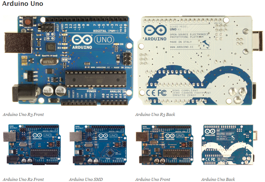
Aruduino Uno 偼ATmega328娃敖偺儅僀僋儘丒僐儞僩儘乕儔丒儃乕僪偩丅 偦傟偵偼侾係杮偺僨僕僞儖擖弌椡僺儞乮偦偺撪俇偮偼 PWM傾僂僩僾僢僩偵巊偊傞乯丄俇偮偺傾僫儘僌擖椡丄16MHz儗僝僱乕僞丄 USB僐僱僋僞丄揹尮僕儍僢僋丄ICSP僿僢僟丄儕僙僢僩儃僞儞偑偁傞丅 儅僀僋儘僐儞僩儘乕儔傪僒億乕僩偡傞慡偰偺暔傪幚憰偟偰偄傞丅 巒傔傞偵偼USB働乕僽儖偱僐儞僺儏乕僞偵偮側偖偐丄傑偨偼AC傾僟僾僞 偵偮側偖偐丄揹抮偵偮側偖偩偗偱偄偄丅