Freescale FRDM-KL46Z の使い方を、「Quick Start Guide」や「FRDM-KL46Z User's Manual」を 中心に日本語で説明する。ソフト開発はCode Warriorを参照の事。Code WarriorとはFreescale社が 出している統合開発環境だ。
このボードを購入したら、先ずwww.freesacle.com の"サイト内検索"で FRDM-KL46Z Quick Start Package を 入れて、このパッケージをダウンロードしよう。パッケージ内にはライセンス・アグリーメントと コンパイル済みの本体用アプリとOpenSDAアプリと、クイック・スタート・ガイドが入っている。これだけでも 結構遊べる。
次に、www.freescal.com/FRDM-KL46Z からユーザーズマニュアルなどもゲットし、暇なときにコードウォリア という巨大アプリ開発環境もダウンロードしておこう。オフライン版は1GBを超える。コードウォリアは 統合開発環境で、アセンブラやC/C++などが込み。無料評価版は利用期間の制限はない。アセンブラも 利用制限はない。しかしこのボード上のMPUはKinetis LシリーズKL46なので、Cコンパイラは64kB制限になる。 なのでこのボードの256kBは全部を利用できないことになる・・・・。
無料でアプリを開発するならmbedの方がいい。このボードはARM mbed availableなのだ。 mbedでの利用はこちら参照
尚、ホビーユースでは、STM32やKinetisなどのARM cortex Mのマイコンボードは、mbed対応品でないと話に ならないと思う。なぜなら開発環境が断然いいからだ。また世界中のエンジニアがライブラリなど情報公開している ので、今後どんどん新製品やプログラム開発が進むだろう。 mbedホームページをみてみよう!! ついでに言えば、STM32ディスカバリ(STM32 discovery)なんか 開発環境がイマイチだねー。買わない方がいいよ。
以下、英文資料の拙訳なので、原文もつけてある。おかしい?と思われた部分は原文を読んでちょ。 れーによって、君もしくは君のシステムが壊れ、あるいはふっとんでも、当局は一切関知しないから そのつもりで。なおこのサイトは自動的に消滅する。成功を祈る。mission impossible
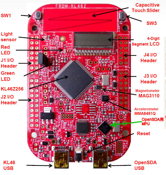 |
特徴 1)ARM社のRISC 32ビットMPUのCortex-M0仕様のMPUを搭載(48MHz動作、256kBフラッシュメモリ、 32kB SRAM) 16bitADコンバータ、12bitDAコンバータ、ハイスピード・コンパレータ、サウンド・オーディオ・インタフェース、 I2C、SPI、6CHタイマ、リアルタイム・クロック 2)各種デバイス搭載(4桁のセグメント表示LCD、タッチスラダ入力装置、ライトセンサ、 地磁気センサ、加速度センサ、LEDやSW) 3)Arduino R3ピン・コンパチの入出力ピン 4)USB接続の強力デバッグ機能(専用MPU搭載)= OpenSDA 5)低価格 \2,500程度 |
Getting Start
[0] Optional: Download and Install the P&E OpenSDA USB Drivers found at www.pemicro.com/opensda.
|
[0](オプション)P&E社のOpenSDA USBドライバをダウロードして、インストする。
ダウンロード・サイト=www.pemicro.com/opensda (訳注)オプションなので必要ではない。
当然、最初からOpenSDA USBドライバはインストされている。 |
FRDM-KL46Z comes with the mass-storage device (MSD) Flash Programmer OpenSDA Application preinstalled. It will appear as a removable storage drive with a volume label of FRDM-KL46Z
|
[1]USBホストパソコンから、ボード上のOpenSDA miniB USBコネクタにつなぐ。
ボードにUSBポートから電源が供給される。 ボードにはOpenSDAアプリの、マス・ストレージ・デバイス(MSD)フラッシュ・メモリ・プログラマが プリインストされている。USBにつなぐと、"FRDM-KL46Z"という名前のリムーバブル・ストレージ・ ドライブとしてみえる。 |
If the USB CDC Serial Port fails to automatically install in Windows, follow the instructions in Step 2. Otherwise, skip to Step 3.
|
マス・ストレージ・デバイス(MSD)フラッシュ・メモリ・プログラマは、バーチャル・シリアル・ポート
も含んでおり、ウィンドウズには適切な .INFファイルが必要。
その.INFファイルは、ステップ0のP&E OpenSDA USB Driversにある。それと
またFRDM-KL46Zのリムーバブル・ドライブにもある。 もしUSB CDCシリアル・ポートがウィンドウズで自動導入に失敗したら、ステップ2 の内容に従ってくれ。失敗しなかったら、ステップ3へ進むように。 |
a. Open Device Manager
b. Locate and right-click on “OpenSDA ? CDC Serial Port”
c. Select “Update Driver Software”
d. ”Browse” and select the FRDM-KL46Z drive
e. Click “Next” to complete the installation
|
[2] a)デバイス・マネジャを開く b)“OpenSDA ? CDC Serial Port”にマウスポインタを合わせ、右クリックする c)“Update Driver Software”を選択する d)”Browse”からFRDM-KL46Z driveを選ぶ e)「次へ」をクリックしてインストを完了 |
|
[3]プリインストされたデモ・プログラムが動作しているKL46MPUではボードの各種機能を
見る事ができる=LCD、eコンパスなど。 (訳者注)自分の場合は、WinVistaのPCにUSB接続しただけで、そのまま[1]にあるように FRDM-KL46Z というドライブが見えた。そして下記にあるように"out of box DEMO"が走り出した。 |
Running "out of box DEMO"
USBをつなぐだけで電源が入り、プリインストされたデモアプリが動き出す。SW1を押していくと 下記のアプリが順に動く。
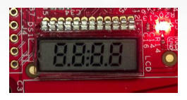 |
1)セグメントLCDのセルフテスト 3秒間、全部のセグメントがオンになる |
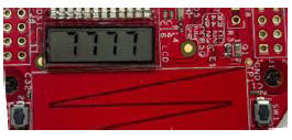 |
2)カウント・アップ・モード 全部の桁が同時にカウント・アップする SW1を押すとスライダ・モードになる |
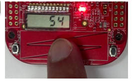 |
3)スライダ・モード キャパシティブ・タッチ・スライダを触るとその相対位置 が表示される。 SW1を押すとeコンパス・モードへ |
||
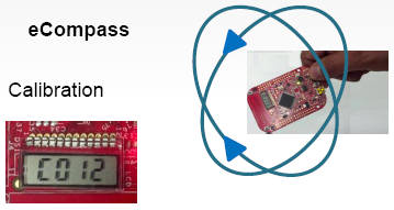 |
4)eコンパス・モード (キャリブレーション)カウンタが100になるまで 本体ボードを全方位に動かす |
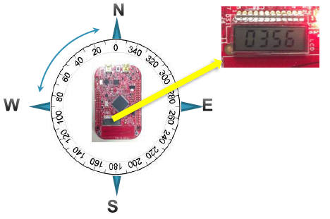 |
本体ボードを回すと、方向が角度でLCDセグメントに
表示される。北を指したとき、LEDが早く点滅する。 SW1を押すとカウンタ・アップ・モードになる |
Introduction to OpenSDA
(訳注) FRDM-KL46Zというボードには、Kinetis Cortex-M0のメインMPUだけでなく、これをUSB経由で パソコンに接続するためのシステムも搭載している。FT232のようにUSBシリアル変換だけするような単純なもの ではなく、専用のMCU(回路図中のU7)を使っている。 このMCUのファームウェアも書き換えできるようになっている。この接続するためのシステムに P&E社のOpenSDAというシステムを採用している。OpenSDAシステムは、メインMPUのプログラム空間を Windowsのファイルシステムとして表示させたり、メインMPUとパソコンをつなぐための仮想シリアル ポートを提供したり、またメインMPUに対する強力なデバッグ機能まで提供するという、 3つの役割を果たしている。 この3つの機能を、専用MCUとそのファームウェアで実現しているのだ。なのでライタのような専用の アダプタインタフェース装置やライタ・ソフトも不要。ボードにPCからUSB接続するだけ。 大変すごい機能のように感じるが、将来的にはマイコン・ボードはみんなこのような形態になっていく事 だろう。開発環境もArduino, mbed, GR-SAKURA のようにオンライン・コンパイラで、誰でも使いやすく、 分かりやすいライブラリや解説が整えられていく事だろう。
以下、その説明が続く。
The MSD Flash Programmer is a composite USB application that provides a virtual serial port and an easy and convenient way to program applications into the KL46Z MCU. It emulates a FAT16 file system, appearing as a removable drive in the host file system with a volume label of FRDM-KL46Z. Raw binary and Motorola S-record files that are copied to the drive are programmed directly into the flash of the KL46 and executed automatically. The virtual serial port can be opened with standard serial terminal applications.
|
「マス・ストレージ・デバイス(MSD) フラッシュ・プログラマ」は仮想シリアルポートと、
KL46Z MCUにプログラム・アプリを送る便利な手段を提供する、複合USBアプリだ。
FAT16ファイルシステムをエミュレートし、パソコンのファイルシステムにリムーバブル・
ドライブとして表示される(ボリュームラベル=FRDM-KL46Z)。 ロー・バイナリと、モトローラSレコード・ファイルをそのドライブにコピーするだけで、 KL46のフラッシュ・メモリに直接プログラムがかかれ、自動で実行される。 仮想シリアルポートはスタンダードなシリアルターミナル・アプリでオープンできる。 |
[1]Locate the Precompiled Example folder in the FRDM-KL46Z Quick Start Package.
[2]Copy & paste or drag & drop one of the .srec files to the FRDM-KL46Z drive.
The new application should now be running on the FRDM-KL46Z drive.
Program FRDMKL46_Demo_freedom.srec example to replace the out-of-box demo on your FRDM-KL46Z drive.
|
MSDフラッシュ・プログラマの使い方 [1]FRDM-KL46Zクイック・スタート・パッケージのPrecompiled Examplesフォルダをみつける [2]xxxx.srecファイルをFRDM-KL46Zドライブに、コピペかドラッグ&ドロップする。 すると、新しいアプリがFRDM-KL46Zドライブ上で動作する。試しに FRDMKL46_Demo_freedom.srec を FRDM-KL46Zドライブ上の"out-of-box demo"(ボードに最初からプリインストされているアプリ) と置き換えてみるといい。 |
[1]Determine the symbolic name assigned to the FRDM-KL46Z virtual serial port. In Windows open Device Manager and look for the COM port named “PEMicro/Freescale ? CDC Serial Port”.
[2]Open the serial terminal emulation program of your choice. Examples for Windows include Tera Term, PuTTY, and HyperTerminal.
[3]Program one of the “serial test” applications from the Precompiled Examples folder using the MSD Flash Programmer.
[4]Configure the terminal program. Most embedded examples use Baudrate115200, 8 data bits, no parity bits, and one stop bit (8-N-1).
[5]Press and release the Reset button (SW1) at anytime to restart the example application. Resetting the embedded application will not affect the connection of the virtual serial port to the terminal program.
NOTE: Refer to the OpenSDA User’s Guide for a description of a known Windows issue when disconnecting a virtual serial port while the COM port is in use.
|
仮想シリアルポートの使い方 [1]FRDM-KL46Zの仮想シリアルポートにつけるシンボルネームを決める。Windowsではデバイス・マネジャ を開き、“PEMicro/Freescale ? CDC Serial Port”という名前のCOMポートを探す。 [2]使っているシリアル・ターミナルのエミュレーション・アプリを開く。Windowsでは例えば、 Tera Term, PuTTY, HyperTerminalなど。 [3]Precompiled Examplesフォルダの中の添付見本アプリから、シリアル・アプリの1つを取り出し、 MSDフラッシュ・プログラマを使ってプログラムする。 [4]ターミナル・プログラムを設定する。ボーレート=115200、8データビット、ノーパリティ、ストップ ビット1(8-N-1)。 [5]添付の見本アプリの開始にはリセットボタンを押して放す。アプリをリセットしても、仮想シリアル ポートとターミナルプログラムの接続には影響しない。 (注)COMポート利用中に仮想シリアルポートが切断されるようなら、既知のWindowsの問題の説明を OpenSDAユーザーズ・ガイドで参照できる。 |
OpenSDA is an open-standard serial and debug adapter. It bridges serial and debug communications between a USB host and an embedded target processor. OpenSDA software includes a flash-resident USB mass-storage device (MSD) bootloader and a collection of OpenSDA Applications. FRDM-KL46Z comes with the MSD Flash Programmer OpenSDA Application preinstalled. Follow these instructions to run the OpenSDA Bootloader and change the installed OpenSDA Application to P&E Debug Application that provides debugging and a virtual serial port all in one application.
|
OpenSDAはオープンスタンダードな、シリアルとデバッグ用アダプタだ。それはUSBホスト(PCとか)と
基板上のプロッセサの間の、シリアル通信やデバッグ接続を実現する。OpenSDAソフトには、USB-MSD(マス・ストレージ
デバイス)のブートローダとOpenSDAアプリ群が含まれる。FRDM-KL46Zには、MSDフラッシュ・プログラマが
プリインストされている。以下の説明では、OpenSDAブートローダを走らせる方法と、インストされている
OpenSDAアプリを入れ換える方法を示す。ここでいうOpenSDAアプリとは、P&E社のデバッグ・アプリで、デバッグ機能
と仮想シリアルポート機能を備えたものだ。 |
[1]Unplug the USB cable if attached.
[2]Press and hold the Reset button
[3]Plug in a USB cable(not included) between a USB host and the OpenSDA USB connector(labeled"SDA") while holding the Reset button.
[4]Release the Reset button.
A removable drive should now be visible in the host file system with a volume label of BOOTLOADER. You are now in OpenSDA Bootloader mode.
|
OpenSDAブートローダ・モードへの入り方 [1]もしつながっていたら、USBケーブルを抜く [2]リセットボタン(SW2)を押したままにして [3]USBホスト(パソコン等)とボードのOpenSDAのUSBコネクタをケーブルでつなぐ。 すると"BOOTLOADER"というボリューム名がファイルシステムで見えるようになる。 |
[1]Locate the OpenSDA Applications folder in the FRDM-KL46Z Quick Start Package.
[2]Copy & paste or drag & drop the Debug Application (DEBUG-APP_Pemicro_v106.SDA) to the BOOTLOADER drive.
[3]Unplug the USB cable and plug it in again. The new OpenSDA Application should now be running and now you can debug your application. For more details on Debug mode or Mass storage application refer to the OpenSDA user’s guide “OPENSDAUG.pdf”
Use this same procedure to load other OpenSDA Applications
|
OpenSDAアプリのロード方法 [1]FRDM-KL46Zクイックスタート・パッケージの中のOpenSDA Applicationsフォルダを見つける。 [2]BOOTLOADERに、デバッグアプリのDEBUG-APP_Pemicro_v106.SDAをコピペする。 [3]USBケーブルを一度抜いてまた差す。すると新しいOpenSDAアプリが動き出し、デバッグ機能が 使えるようになる。デバッグモードやマス・ストレージ・アプリについて詳細を知りたい場合は、 OpenSDAユーザーズガイド(OPENSDAUG.pdf)を参照されたし。 これと同じような方法で、他のOpenSDAアプリをロードできる。 |
FRDM-KL46Z User's Manual
1 FRDM-KL46Z Overview
The Freescale Freedom development platform is a set of software and hardware tools for evaluation and development. It is ideal for rapid prototyping of microcontroller-based applications. The Freescale Freedom KL46Z hardware, FRDM-KL46Z, is a simple, yet sophisticated design featuring a Kinetis L series microcontroller, built on the ARM Cortex-M0+ core.
FRDM-KL46Z can be used to evaluate the KL46, KL36, KL26 and KL16 Kinetis L series devices. It features a MKL46Z256VLL4, this device boasting a max operating frequency of 48MHz, 256KB of flash, 32KB RAM, a full-speed USB controller, segment LCD controller, and loads of analog and digital peripherals. The FRDM-KL46Z hardware is form-factor compatible with the Arduino R3 pin layout, providing a broad range of expansion board options. The on-board interfaces includes a 4 digit segment LCD, a 3-axis digital accelerometer, magnetometer, capacitive touch slider, and ambient light sensor.
The FRDM-KL46Z features the Freescale open standard embedded serial and debug adapter known as OpenSDA. This circuit offers several options for serial communications, flash programming and run-control debugging.
|
Freescale社のFreedom開発プラットフォームは、評価・開発用のソフトとハードのセットになっている。
マクロコントローラ搭載システムのプロトタイピング開発にはもってこい。FRDM-KL46Zは
ARM Cortex-M0+コアベースのKinetis Lシリーズのマイクロコントローラを搭載した、シンプルで
洗練されたデザインだ。 FRDM-KL46Zは、Kinetis Lシリーズの評価用にも利用できる。MKL46Z256VLL4がメインプロセッサで、 最大動作周波数は48MHz、フラッシュメモリは256KB、RAMは32KB、フルスピードUSBコントローラ付き、 セグメントLCDコントローラ付き、その他たくさんのアナログ/デジタル周辺装置を搭載している。 そしてArduino R3のピン・レイアウトと互換性がある。またオンボードの4桁LCD、3軸加速度センサ、 磁気センサ、静電容量式タッチセンサ、光センサーがある。 ボードにはオープン・スタンダードのシリアル・デバッグ・アダプタのOpenSDAが付属する。この回路は シリアル通信とフラッシュ・プログラミングと、run制御できるデバッグ機能を提供する。 |
2 References documents(参考文献)
The table below provides a list of reference documents for the FRDM-KL46Z hardware. All of these documents are available online at www.freescale.com/FRDM-KL46Z. ==下表はボードの参考文献リスト。 www.freescale.com/FRDM-KL46Zから全部入手可能。
| ファイルネーム | 内容 |
| FRDM-KL46Z Quick Start Package | クイックスタート・ガイドや、ゲッティング・スタート用ファイル |
| FRDM-KL46Z User’s Manual | ボードの概要や詳細情報 |
| FRDM-KL46Z Pinouts | MPUの全接続ピンのスプレッドシート、I/Oヘッダピンのレイアウト、ArduinoR3の ピン互換性チャート、OpenSDA用MCUのピンレイアウト。 |
| FRDM-KL46Z Schematics | ボード回路図のPDF |
| FRDM-KL46Z Design Package | デザイン・ソース・ファイル |
| OpenSDA User’s Guide | OpenSDAの利用説明書 |
3 Getting started
Refer to the FRDM-KL46Z Quick Start Package for step-by-step instructions for getting started with the FRDM-KL46Z. See the Jump Start Your Design section on http://www.freescale.com/FRDM-KL46Z for the Quick Start Package and software lab guides.
|
FRDM-KL46Z Quick Start Packageにゲティング・スタートがステップバイ・ステップで
説明されているので、参照のこと。 http://www.freescale.com/FRDM-KL46Z のジャンプ スタート・セクションを見ろ。 |
4 FRDM-KL46Z Hardware Overview
・MKL46Z256VLLZ4 MCU (48 MHz, 256KB Flash, 32 KB RAM, Low power, 100LQFP package)
・Dual role USB interface with mini-B USB connector
・Open SDA
・4 digit segment LCD module
・Capacitive touch slider
・Ambient light sensor
・MMA8451Q accelerometer
・MAG3110 Magnetometer
・2 user LEDs
・2 user push buttons
・Flexible power supply options = USB, coin cell battery, external source
・Battery-ready, power-measurement access points
・Easy access to MCU I/O via Arduino R3 compatible I/O connectors
・Programmable OpenSDA debug interface with multiple applications available including:
・Mass storage device flash programming interface
・P&E Debug interface provides run-control debugging and compatibility with IDE tools
・CMSIS-DAP interface: new ARM standard for embedded debug interface
・Data logging application
・Arduino R3 compatibility
<Fig1 ブロックダイヤグラム>
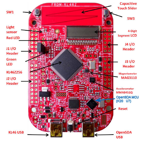
<Fig2 部品配置>
5 FRDM-KL46Z Hardware Description
5.1.1 Power Supply
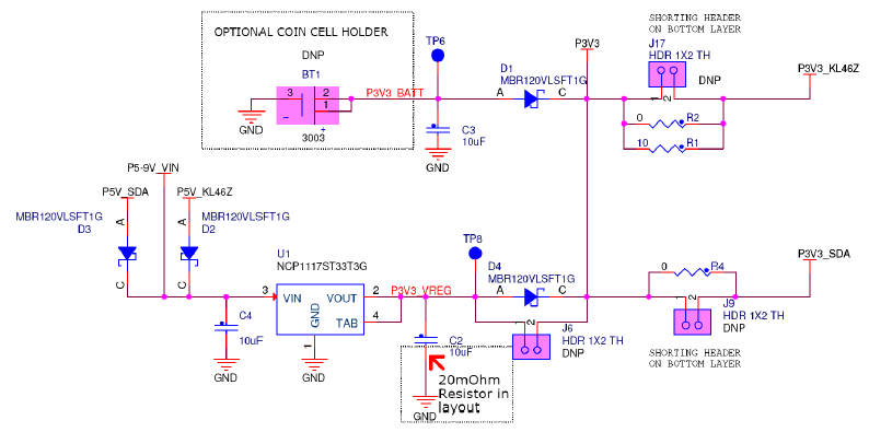
There are multiple power supply options on the FRDM-KL46Z. It can be powered from either of the USB connectors, the VIN pin on the I/O header, an on-board coin cell battery, or an off-board 1.71-3.6V supply from the 3.3V pin on the I/O header. The USB and VIN supplies are regulated on-board using a 3.3V linear regulator to produce the main power supply. The other two sources are not regulated on-board. Table 2 provides the operational details and requirements for the power supplies.
Note that the OpenSDA circuit is only operational when a USB cable is connected and supplying power to OpenSDA USB. However, protection circuitry is in place to allow multiple sources to be powered at once.
|
FRDM-KL46Zには複数の電源オプションがある。USBコネクタ、I/OヘッダのVINピン、
コイン電池、I/Oヘッダの3.3Vピン(1.71-3.6V 供給)など。USBとVINピンからの入力電源
は主電源を作るために、3.3Vレギュレータに入る。他の2つはレギュレータには入らない。
表2に詳細動作と電源要件がある。 (注)OpenSDAは、OpenSDA USBにケーブルが接続された時だけ、動作する。保護回路が あるので、複数電源入力は可能だ。 <表2 電源の要件>
|
| 回路図中の名前 | 説 明 |
| P5-9V_VIN | I/OヘッダのVINピン(J9 16番ピン)から。ショットキー・ダイオードによる 逆電圧保護あり。 |
| P5V_SDA | OpenSDA USB コネクタから。ショットキー・ダイオードによる 逆電圧保護あり。 |
| P5V_KL46Z | KL46Z USBコネクタから。ショットキー・ダイオードによる 逆電圧保護あり。 |
| P3V3_VREG | レギュレータからの3.3V。P3V3線へのソース電源。 ショットキー・ダイオードによる逆電圧保護あり。(注1) |
| P3V3_BATT | ボタン電池から。P3V3線へのソース電源。 ショットキー・ダイオードによる逆電圧保護あり。 |
| P3V3 | FRDM-KL46Zのメイン電源線。P3V3_VREG, P3V3_BATT, I/0ヘッダ(J9 8番ピン) から供給される。 |
| P3V3_KL46Z | KL46Z MCUへの供給。ヘッダピンJ17は消費電力を計測するの便利な機能を提供する。(注2) |
| P3V3_SDA | OpenSDA回路への供給。ヘッダピンJ9は消費電力を計測するの便利な機能を提供する。 (注2) |
| P5V_USB | I/Oヘッダ(J3 10番ピン)への名目上の5V供給。P5V_K20D50MかP5V_ODSAから つながっている。ショットキー・ダイオードによる逆電圧保護あり。 |
|
(注1)デフォルトのレギュレータ(U1)は3.3V出力。しかしユーザで構成を修正して、
1.8Vや2.5Vなどのレギュレータも利用可能。KL46マイクロコントローアは1.71Vから
3.6Vまでの動作範囲がある。 (注2)J17とJ9はデフォルトでは付いていない。この2本のピンはプリント基板のトレースで ショートされている。Kl46やOpenSDAのMCUの消費電力を計測するには、まず最初にこの2ピン のトレース(回路の線)をカットしなければならない。そすれば電流計プローブや直列抵抗と 電圧計でこれらのレール(電源ライン)の消費電力を計測できる。 1) By default the linear regulator, U1, is a 3.3V output regulator. However, this is a common footprint that would allow the user to modify the assembly to utilize an alternative device such as a 1.8V or 2.5V regulator. The KL46 microcontroller has an operating range of 1.71V to 3.6V 2) J17 and J9 are not populated by default. The two pins of these headers are shorted together by a trace on the bottom layer of the PCB. To measure the energy consumption of either the KL46 or the OpenSDA MCU, the trace between these pins must first be cut. A current probe or a shunt resistor and voltage meter can then be applied to measure the energy consumption on these rails. |
5.1.2 Serial and Debug Adapter (OpenSDA)
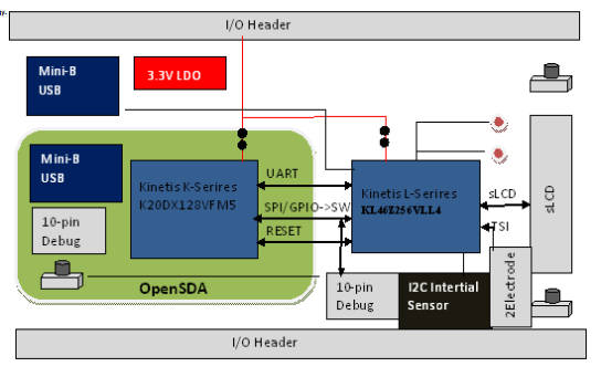
OpenSDA is an open-standard serial and debug adapter. It bridges serial and debug communications between a USB host and an embedded target processor as shown in Figure 4. The hardware circuit is based on a Freescale Kinetis K20 family microcontroller (MCU) with 128 KB of embedded flash and an integrated USB controller. OpenSDA features a mass storage device (MSD) bootloader, which provides a quick and easy mechanism for loading different OpenSDA Applications such as flash programmers, run-control debug interfaces, serial-to-USB converters, and more. Refer to the OpenSDA User’s Guide for more details.
|
OpenSDAはオープンスタンダードのシリアル通信とデバッグを提供するアダプタ・システム(ソフトとハード)だ。
Fig4にあるとおり、
それはUSBホスト(パソコンとか)とボード上のプロセッサ間に位置し、シリアル通信とデバッグのための接続
機能を実現している。
その様子はfig4のとおり。そのハードウェアはFreescale社のK20ファミリのMCUだ(128kBフラッシュメモリとUSB
コントローラ内蔵)。OpenSDAはMSD(マス・ストレージ・デバイス)ブートローダ機能を提供し、フラッシュ・プログラマ機能、
ラン制御デバッグ機能、シリアルUSBコンバータ機能などを実現する。詳細はOpenSDAユーザーズガイド参照のこと。 |
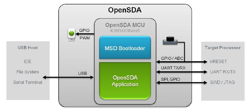
OpenSDA is managed by a Kinetis K20 MCU built on the ARM Cortex-M4 core. The OpenSDA circuit includes a status LED (D8) and a pushbutton (SW2). The pushbutton asserts the Reset signal to the KL46 target MCU. It can also be used to place the OpenSDA circuit into Bootloader mode. SPI and GPIO signals provide an interface to either the SWD debug port of the K20. Additionally, signal connections are available to implement a UART serial channel. The OpenSDA circuit receives power when the USB connector J13 is plugged into a USB host.
| OpenSDAはARM Cortex-M4コアのKinetis K20 MCU 上で動作している。その回路にはステータスLED(D8)と SW2が含まれる。SW2はメインCPUのKL46にリセット信号を送る。またこのSW2はOpenSDAをBootloaderモード にする時にも使う。SPIとGPIO信号は、K20のSWDデバッグ・ポートにもインタフェースを提供している。 UARTのシリアル・チャネルの接続も可能である。OpenSDA回路はUSBコネクタJ13にUSBホストが接続されると 電源が供給される。 |
Signals with SPI and GPIO capability are used to connect directly to the SWD of the KL46. These signals are also brought out to a standard 10-pin (0.05”) Cortex Debug connector (J11). It is possible to isolate the KL46 MCU from the OpenSDA circuit and use J11 to connect to an off-board MCU. To accomplish this, cut the trace on the bottom side of the PCB that connects J18 pin 2 to J11 pin 2. This will disconnect the SWD_CLK pin to the KL46 so that it will not interfere with the communications to an off-board MCU connected to J11.
|
デバッグ・インタフェース SPIとGPIOの信号は、KL46のSWDに直接接続するために利用される。この信号は10ピンCortexデバッグ・ コネタク(J11)にも出ている。KL46 MCUをOpenSDA回路から切り離し、別のMCUにJ11を使う事もできる。 これをするには、プリント基板の裏のJ18の2番ピンとJ11の2番ピンをつなぐトレース(接続線)を切る。 そうすると、KL46に入るSDW CLKピンが切り離されて、J11に接続される別のMCUへの接続を妨げ なくなる。 |
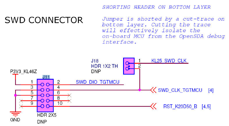
Note that J11 is not-populated by default. A Samtec FTSH-105-02-F-D or compatible connector can be added to the J11 through-hole connector. A mating cable, such as a Samtec FFSD IDC cable, can then be used to connect from the OpenSDA of the FRDM-KL46Z to an off-board SWD connector.
|
(注)J11はデフォルトでは装備されていない。Samtec社のFTSH-105-02-F-Dかそのコンパチ・コネクタ
がJ11のスルーホールに入る。Samtec社のFFSD IDCケーブルのような接続ケーブルで、FRDM-KL46Zの
OpenSDAとボード外のSWDコネクタで接続する。 |
MKL46Z4 Microcontroller
FRDM-KL46ZボードのマイクロプロセッサはKinetis LシリーズのKL462Z256VLL4だ
|
32-bit ARM Cortex-M0+ core ○最大48MHz 動作 ○シングル・サイクルの高速I/Oアクセス メモリ ○256kBフラッシュメモリ ○32kB SRAM 内蔵システム ○パワーマネジメント ○モード・コントローラ ○低電流ウェークアップ・ユニット ○リード・モディファイ・ライト操作のビット処理エンジン ○DMAコントローラ (Direct Memory Access) ○コンピュータ正常動作監視用のウォッチドッグ・タイマ クロック ○システム用、CPUクロック用のFLLとPLL付クロック生成モジュール ○4MHzと32KHzの内部参照クロック ○外付けクリスタル・レゾネータをサポート可能なシステム・オシレータ ○リアルタイムクロック(RTC)やウォッチドッグタイマ用の低消費電力型1kHzRCオシレータ 汎用通信機能 ○I2Sオーディオ・インタフェース1セット ○8bit SPI 2セット ○FS/LS送受信機能が組み込みの、2機能USBコントローラ ○USB電源レギュレータ ○I2Cモジュール2セット ○低電力UART1セット、標準UARTモジュール2セット タイマ ○6CHタイマ/PWMモジュール ○2CHタイマ/PWMモジュール2セット ○2CH汎用の割込タイマ(PIT) ○リアル・タイム・クロック ○低電力タイマ ○システム・タイマ マン・マシン・インタフェース ○セグメントLCDコントローラ 最大表示は8×47桁または4×51桁 ○汎用入出力コントローラ ○静電容量型タッチセンサ入力インタフェースのハードウェア |
5.1.3 Clock source
The Kinetis KL46 microcontrollers feature an on-chip oscillator compatible with three ranges of input crystal or resonator frequencies: 32-40 kHz (low freq. mode), 3-8 MHz (high freq. mode, low range) and 8-32 MHz (high freq. mode, high range). The KL46Z256on the FRDM-KL46Z is clocked from an 8 MHz crystal..
|
Kinetis KL46 マイクロコントーラは、オンチップ・オシレータの機能がある。それは
水晶やレゾネータ発振子の3つのレンジで可能だ。32-40kHz(低速周波数モード)、3-8MHz
(高速周波数モード・低レンジ)、8-32MHz(高速周波数モード・高レンジ)。FRDM-KL46Zは
8MHZ水晶子クロックを利用。 |
5.1.4 USB Interface
The Kinetis KL46 microcontrollers feature a dual-role USB controller with on-chip full-speed and low-speed transceivers. The USB interface on the FRDM-KL46Z is configured as a full-speed USB device. VREGIN must be powered to enable the internal circuitry of USB (by jumper J7)
| Kinetis KL46マイクロコントローラは、オンチップで、2つのUSBコントローラ機能がある(フルスピードと ロースピード)。FRDM-KL46ZではフルスピードのUSBデバイスとして設定されている。内蔵のUSB回路を 有効にするには、VREGINに電源をつなぐ必要がある(ジャンパJ7)。 |
5.1.5 Serial Port
The primary serial port interface signals are PTA1 UART0 RX and PTA2 UART0_TX. These signals are connected the OpenSDA
| メインのシリアルポート・インタフェース信号は、PTA1 UART0 RXとPTA2 UART0 TXだ。この信号線は OpenSDAに接続されている。 |
5.1.6 Reset
The RESET signal on the K20 is connected externally to a pushbutton, SW2, and also to the OpenSDA circuit. The reset button can be used to force an external reset event in the target MCU. The reset button can also be used to force the OpenSDA circuit into bootloader mode. Please refer to section 5.2, Serial and Debug Adapter (OpenSDA), for more details.
| K20のRESET信号は外部のプッシュボタンSW2に接続されている。またOpenSDA回路にもつながって いる。リセットボタンは、ボード上のマイクロプロセッサに外部リセット・イベントを発生される ために利用される。またOpenSDA回路をBOOTLOADERモードにするのにも利用できる。更に詳細な 事は、5.2 Serial nad Debug Adapter(OpenSDA)を参照してくれ。 |
5.1.7 Debug
The sole debug interface on all Kinetis L Series devices is a Serial Wire Debug (SWD) port. The primary controller of this interface on the FRDM-KL46Z is the onboard OpenSDA circuit (see section 5.2). However, an unpopulated 10-pin (0.05”) Cortex Debug connector, J11, provides access to the SWD signals. The Samtec FTSH-105-02-F-D or compatible connectors can be added to the J11 through-hole debug connector to allow for an external debug cable to be connected.
| Kinetis Lシリーズデバイスのソロ・デバッグ・インタフェースはシリアル・ワイヤー・ デバッグ(SWD)ポートだ。FRDM-KL46Zのこのインタフェースのメインコントローラは ボード上のOpenSDA回路だ(5.2参照)。しかし未搭載の10ピンCortexデバッグ・コネクタJ11は SWD信号への接続を提供している。FTSH-105-02 F-DコネクタかコンパチコネクタをJ11に 外部デバッグケーブルが接続できる。 |
5.1.8 Segment LCD
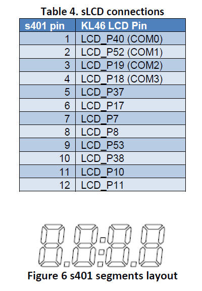
FRDM-KL46Z is using a 4 digit display (LUMEX LCD-S401M16KR) 4x8 segments. following table shows connection from KL46 to s401 display.
|
FRDM-KL46Zは4桁ディスプレイ(LUMEX LCE-S401M16KR 4x8セグメント)を使っている。次の表は
KL46からS401ディスプレイへの接続示す。 |
5.1.9 Capacitive Touch Slider
Two Touch Sense Input (TSI) signals, TSI0_CH9/PTB16, and TSI0_CH10/PTB17 are connected to capacitive electrodes configured as a touch slider. Freescale’s Touch Sense Software (TSS) provides a software library for implementing the capacitive touch slider.
| 2つのタッチ・サンサ入力信号(TSI: TSI0_CH9/PTB16と TSI0_CH10/PTB17)はタッチスラダの 容量性電極に接続されている。Freescale社のタッチセンサ・ソフトウェア(TSS)は容量性タッチ スライダを導入するためのソフトウェア・ライブラリを提供している。 |
5.1.10 Three-axis Accelerometer
A Freescale MMA8451Q low-power, three-axis accelerometer is interfaced through an I2C bus and two GPIO signals as shown in Table 5 below. By default, the I2C address is 0x1D (SA0 pulled high).
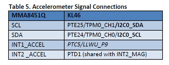
|
Freescale社のMMA8451Q低消費電力の3軸加速度計は、下表のように、I2Cバスと2つのGPIO信号
に接続されている。デフォルトでは、I2Cアドレスは0x1D(SA0プルアップ)。 |
5.1.11 Three-axis Digital Magnetometer
A Freescale MAG3110 Three-Axis, Digital Magnetometer is interfaced through an I2C bus, and one GPIO signals as shown in Table 6 below
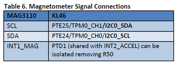
| MAG3110 3軸デジタル地磁気センサーは下表のとおり、I2Cバスと1つのGPIO信号に接続されている。 |
5.1.12 LEDs
Two LED, Green LED is PWM capable, Signal connections are shown in Table 7.
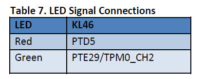
| 2つのLED、緑のLEDはPWM可能。信号は下表のとおり接続されている。 |
5.1.13 Visible light sensor
The FRDM-KL46Z has a visible light sensor that is connected to ADC0_SE3
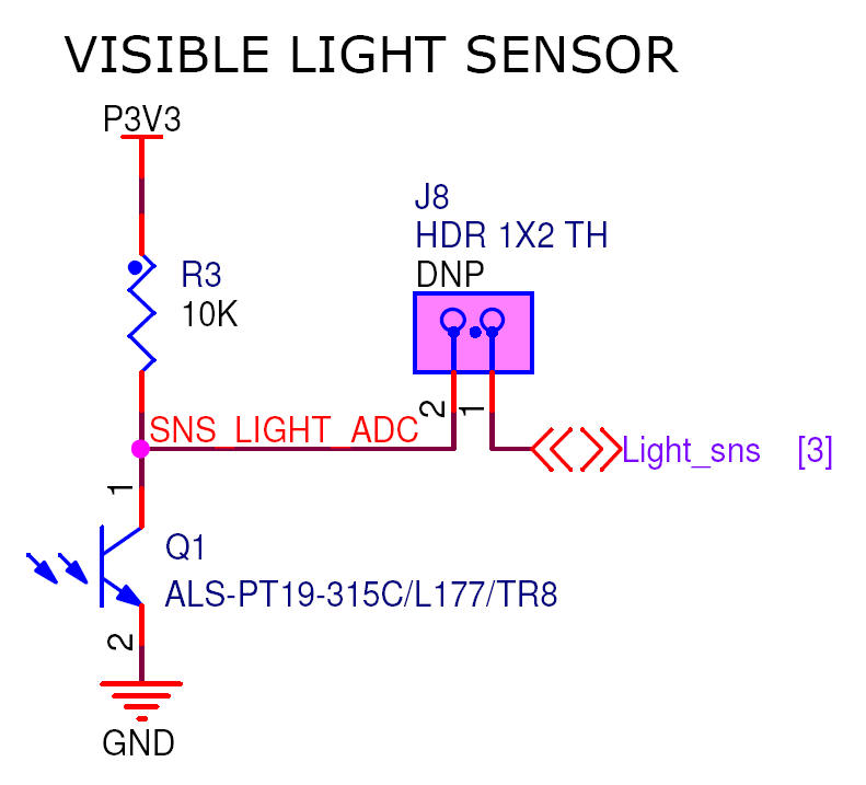
|
可視光サンサがあり、ADC0_SE3 に接続されている。 |
5.1.14 Input/Output Connectors
The MKL46Z256VLL4 microcontroller is packaged in a 100-pin LQFP. Some pins are utilized in on-board circuitry, but many are directly connected to one of four I/O headers.
The pins on the KL46 microcontroller are named for their general purpose input/output port pin function. For example, the 1st pin on Port A is referred to as PTA1. The I/O connector pin names are given the same name as the KL46 pin connected to it, where applicable.
Note that all pinout data is available in spreadsheet format in FRDM-KL46Z Pinouts. See the Reference Documents section for details.

|
MPUは100ピンLQFPパッケージだ。複数のピンはボード上の回路で利用されている。しかしたくさんの
ピンは直接4つのI/Oヘッダピンのどれかに接続されている。
KL46MPUのピンはそれぞれ汎用の入出力ピンの機能に従って名前が付されている。例えばポートAの第1ピン
はPTA1になっている。I/Oコネクタピンの名前は可能な範囲で、KL46ピンと同じ名前を付けている。 注:全てのピンレイアウトは、FRDM-KL46Zのスプレッドシート・フォーマットでも有効だ。詳細はリファレンス・ ドキュメントを参照せよ。 |
5.1.15 Arduino Compatibility
The I/O headers on the FRDM-KL46Z are arranged to allow compatibility with peripheral boards (known as shields) that connect to Arduino and Arduino-compatible microcontroller boards. The outer rows of pins (the even numbered pins) on the headers share the same mechanical spacing and placement as the I/O headers on the Arduino Revision 3 (R3) standard.
| ボードのI/Oヘッダは、Arduinoやその互換マイコンボードにつなげられる汎用ボード(いわゆるシールド) に互換性がある。ヘッダの外側のピンの列(ピン番号はふられている)は、物理的位置もArduinoR3 の標準仕様とまったく同じになっている。 |
mbed での利用
mbedとはネット上でプログラムをコンパイルして、それをマイコンボードに ダウロードして、動作させる事ができるサイトだ。<mbed.org> 参照。mbedのサイト でプログラム開発ができるのは、mbed対応のマイコンボードだけ。現状ARM社設計仕様のCortex-M0やM3を コアにした、MPU搭載のボード(MPUメーカ、ボードメーカは色々ある)。
mbed.orgのサイトの[Platforms]ボタンを押して、購入した自分のマイコンボードを選択することから 始める。
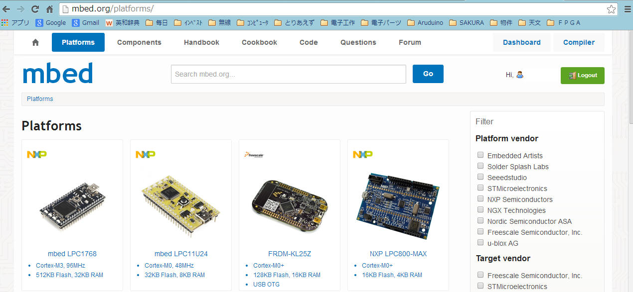
FRDM-KL46Zでmbedを利用する概要を書く。まず[Platforms]でFRDM-KL46Zを選び、mbed用ファームウェアを ダウンロードし、ボードのresetSWを押しならパソコンにUSB接続する。するとボードは"bootloaderモード" で立ち上がるので、mbed用ファームウェアをbootloaderドライブにコピー&ペーストする。 そして一旦USBを切り離し、 再度接続するとこのボードはmbed仕様でパソコンにつながり、"mbed"ドライブが見えるようになる。 一旦このようにmbed仕様にすると、デフォルトの"FRDM-KL46Z"ドライブはもはや見えなくなる。
ボードはそのままで、次にmbed.orgのサイトで自分のアカウントを新規登録してログインする。その状態 でmbedドライブの中のmbed.htmをクリックすると、FRDM-KL46Zが自分のアカウント内で、 自分の使っているボードとして登録されて、[compiler] が使えるようになる。mbed.orgの最上段右端の[Compiler]ボタンを押してみよう。
ここから先、mbed上でプログラミング、コンパイラ、ダウンロードなどの方法を確認してくれ。
もどる