|
シリアルEEPROMデータシートと使い方 M6M80011AP, L, FP 1024bit ( 64word by 16bit ) |
|
・16ビットデータ×64アドレスのシリアル式EEPROM ・アドレスは<A0-A5>(6ビット)で指定、データ幅は<D0-D15>(16ビット)。 ・モードには「リード」、「ライト」、「ライト・イネーブル(WEN)」、「ライト・ディスイネーブル(WDS)」、 「ステータス・アウトプット」の5種類がある。その手順の記載がなくて、分かりにくい。下記参照 ・ライト動作にはIC内部で時間がかかるよう。それをRDY/BUSY(-)ピンで見ながら操作するみたい。 ・でもそのライト動作中にリードなどができるような記載が散見される。 ・"interconnect"という語が使われているが、ピン同士を接続して1本化して使う事のようだ。 「DIとDO」、「CS(-)とRESET」を接続して1つのピンとして使うようだ。 ・データシート中、モードの手順について説明がない(さすが三ビジ)。「Status Outputモード」の説明の所参照。 1)書き込み操作は、ライト・イネーブル・フラグ="0"の時だけ可能。 2)このフラグの操作は"ライト・イネーブル・モード"か、"ライト・ディスエーブル・モード"でしかできない(みたい)。 3)電源ON時にライト動作のためには、先ず"ライト・イネーブル・モード"にする必要がある。 4)一度WENモードにすれば(電源ONの間は)ラッチが有効。 5)読み出しはWEN/WDSのモードにかかわらず、いつでも可能。 |
|
Pin Configration Top view 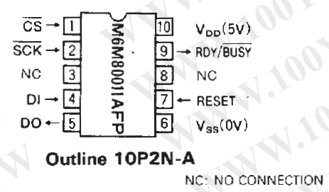
|
<特色> ・5V単一電源 ・クロック同期のシリアルI/O ・3つの制御ポートがある(CS(-1)、DI、DO ) ・組み込みシーケンシャル制御 ・10万回消去 ・10年データ保持 <応用> 電子チューナの不揮発チャネルメモリなど、それほどメモリ内容を頻繁に 書き換えない用途に向く。 <機能> M6M80011APはクロック式シリアルポート・コンパチのEEPROMである。 データはクロックの立ち上がりエッジで入力され、 クロックの立下りエッジで出力される。最初の8ビットでモードを記述し、 次の8ビットでアドレスを記述し、続く16ビットでI/Oデータを示す。 5つのどのモードを記述してもよい。(write、read、write enable、status output) ライトタイム(書き込みに要する時間)は内蔵マイマで設定されている。 ICがライト動作中かそうでないかは、RDY/BUSY(-)ピンの状態でわかる。 あるいはステータス・モードがセットされたあとのDOピンの状態でもわかる。 M6M80011AP is a clocked serial port compatible EEPROM, and data is input from the rising edge of clock signal and output by synchronizing to the falling edge of clock signal. Data is grouped by 8bits. The beginning 8bits specify the mode, next 8bits specify the address, and subsequent 16 bits specify I/O data. Any of five modes(write, read, write enable, write disable, status output) may be specified. The write time is set by an internal timer, and determination of whether write operation is in progress or not can be made from status of the RDY/BUSY(-) pin or the DO pin status after the status mode has been set. |
| ピン説明 |
| CS(-) | チップセレクト |
1)チップの選択は、このピンを”L”にする事で行う。 ”H”のとき、内蔵のシーケンシャル・コントローラはリセットになる。 それゆえ、このピンは各モードを実行する前に、”H”にして おかなければいけない。 2)ライト動作中(BUSY出力が"L"のとき)、 このピンへの入力にかかわらず、ライト動作は継続する。 3)ライト動作が終了したあと、モードを リード可能にするためには、このピンは”H”にしなけれ ばいけない。 ”status output”モードのときだけ、シーケンシャル・ コントローラがリセットされ、そしてライトオペレーション 開始以来”tSTA”が続いていれば、このピンが”L”でも リーディングは可能。 |
| SCK(-) | クロック入力 |
1)入力データはクロックの立ち上がりエッジで読まれる 2)データはクロックの立下りエッジに同期して出力される |
| DI | データ入力 |
データはこのピンから入力する。 |
| DO | データ出力 |
データはこのピンから出力される。DIとDOは相互接続(1本化)できる。 |
| RESET | リセット入力 |
1)電源のON/OFF時は”H”に設定されなければならない。 2)このピンが”H”に設定されているとき、シーケンシャル ・コントローラと書き込み回路はメモリ保護のためにリセット される。もしこのピンが書き込み操作の間に”H”になると、 動作はホルトされる。 3)このピンとCS(-)は相互接続(1本化)できる。もしそうすると、 CS(-)(=RESET)は書き込み動作中、”L”に保持されなけ ればならない。 |
| RDY/BUSY(-) | ビジー出力 |
1)書き込み動作中、これは”L”になる。 2)電源のON/OFF時、これは”L”になる。 この条件下では全ての入力は動作しない。 |
| モード・ファンクション |
| モード名 | モード | アドレス | データ | ファンクション |
| Read | 10101000 | A0A1A2A3A4A5 00 | D0~D7D8~D15 | アドレスからのリード <A0~A15> |
| Write | 10100100 | A0A1A2A3A4A5 00 | D0~D7D8~D15 | アドレスへのライト <A0~A15> |
| Write enable | 10100011 | XXXXXXXX | -- | ライト・オペレーションがイネーブル |
| Write disable | 10100000 | XXXXXXXX | -- | ライト・オペレーションがディスイネーブル |
| Status output | 10101001 | 00XXXXXX | 0(Busy) 1(Ready) | ブジー・フラグ |
| 10XXXXXX | 0(Enable) 1(Disable) | ライト・イネーブル・フラグ | 01XXXXXX | 0(Correct) 1(incorrect) | ECCフラグ |
|
Status Output モードの説明 (1)ビジーフラグ ビジーフラグはBUSY(-)出力ピンと同じ機能を提供する。 このフラグが記されると、16クロックの立下りエッジから のreadyで、”1”が出力される。そしてもしビジー (ライト操作中)なら”0”が出力される。 (2)ライト・イネーブル・フラグ このICはライト・イネーブル・フラグを持っている。 書き込み操作はこのフラグが”0”のときだけ実行される。 このフラグの中身はライト・イネーブル(WEN)モードと ライト・ディスエイブル(WDS)モードの中でのみ更新可能。 電源ON時はこのフラグの中身は未設定。そのため、書き込み 操作のためのライト・モードのセッティングよりまえに、 WENモードが設定されなければならない。 一度WENモードが設定され、このフラグがイネーブル状態に 設定されると、WDSモードが設定されるまで、ラッチは有効である。 このフラグのステータスにかかわらず、EEPROMの 読み出しは可能である。 (3)ECCフラグ データエラーを修正するECC回路はメモリ・セルの 信頼度を高いレベルで保障するために組み込まれている。 ECC回路は、1ワード(16ビット)中の上位8ビット、 下位8ビットそれぞれで、1ビットだけエラーがあったときに、 データエラーを修正し、修正されたエラーを出力する。 上位または下位のバイトの少なくとも1つでエラーが 修正されたときに、このフラグは1にセットされ、 エラー修正がなされた事を示す。このようにデータは 修正される。このフラグが”0”のときは、ECC回路を 動作させる事なく、正しいデータ値が出力された事を示す。 リード・モードのあと、ECCモードに設定することで、 その直前に記されたアドレス上のECC情報が確認できる。 |
|
タイミング・ダイヤグラム (1)同期データI/Oタイミング 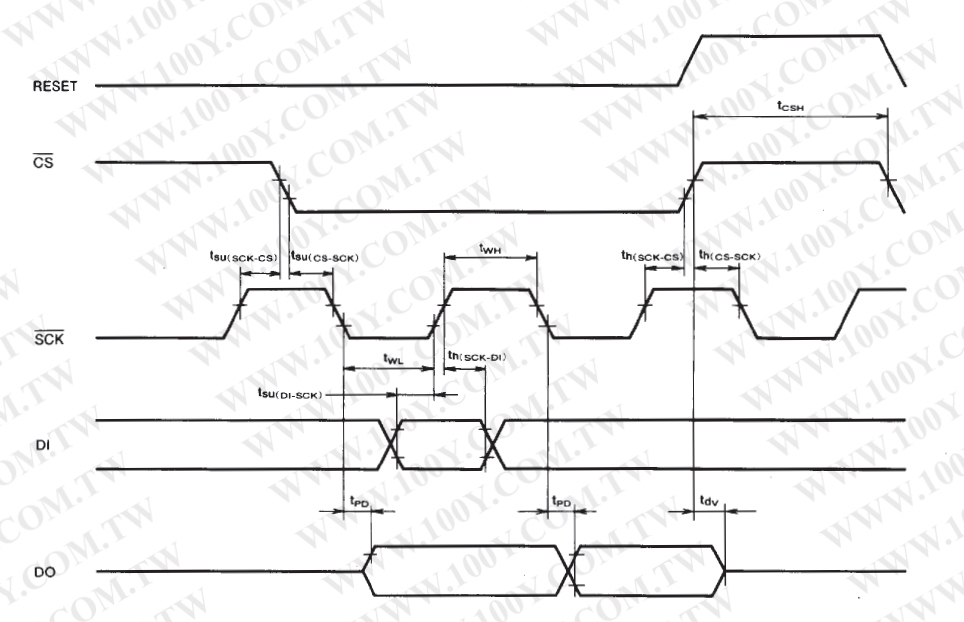 (2)毎8クロックごとのSCK(-)"H" ホールド時間 上記のタイミング・パタンは8ビットデータの転送の間は維持される。 しかし全モードでSCK(-)入力のためには、クロックの"H"ホールド時間 (twwh)は8番目のクロックごとに必要である。 |
| tWH | Positiv data shift clock pulse width | Min 450 ns |
| tWL | Negative clock pulse width | Min 450 ns |
| tWWH | Clock hold time ( every 8 clocks) | Min 4 us |
| tSU(CS-SCK) | Chip select set ut time before the fall of the clock | Min 1 us |
| th(SCK-CS) | Chip select hold time after the rise of the clock | Min 4 us |
| tSU(DI-SCK) | Data set up time before the rise of the clock | Min 150 ns |
| th(SCK-DI) | Data hold time after the rise of the clock | Min 200 ns |
| tSU(SCK-CS) | Clock set up time before the fall of the chip select | Min 1 us |
| th(CS-SCK) | Clock hold time after the rise of the chip select | Min 1 us |
| tPD | Data delay time after the fall of the clock | MAX 350 ns |
| tdv | Data valid time after the rise of the chp select | MAX 1 us |
| tE/W | Selftime write sequence time | MAX 15 ms |
| tCSH | Positive chip select width | Min 4 us |
| thw | Chip select, clock hold time after the start of the write sequence | Min 4 us |
| tSAT (note1) | At setting status mode, clock hold time start of the write sequence when CS is 0 | Min 12 us |
| Note1 tSTA indicates the maximum value of the sequential controller rest pulse that is generated after the write operation is started. When the sequential controller is reset, only the status output can be read. |
|
各モードのタイミングチャート (1)CS(-)とRESETピンを操作する場合 Write enable と Write disable モード 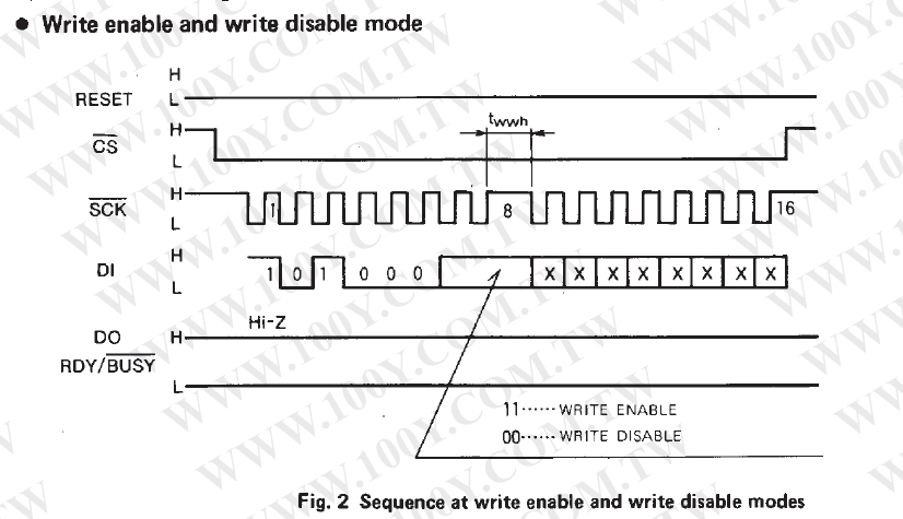 -------------------------------------------- Status outputモード D0ピンから書き出される各stausフラグの状態は 16番目のクロックの立ち上がりエッジから開始される出力だ。 出力はクロックに依存しないがCS(-)が"H"になるまで続く。 The status of each status flag specified from the D0 pin is output starting at the rising edge of the 16th clock. Output is not dependent on clock but continues until CS(-) becomes "H". 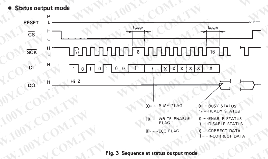 -------------------------------------------- リードモード 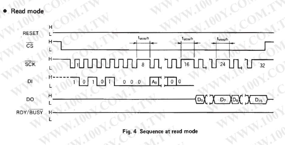 -------------------------------------------- ライトモード ライト動作の実行は32番目クロックの立ち上がりエッジでスタートする。 ライト動作中は、CS入力値は"H"か"L"のどちらかになるだろう。 もしライド動作中にCS(-)ピンが"L"になっていると、リード動作はStatusモード の時のみ可能。このようにライト動作中は、SCK(-)は他のタスクのために利用されるべきだ。 CS(-)はFig6のように"H"に設定されているべきだ。 (たとえCS(-)が"L"であっても、もしダミービットがFig10のように入っていれば SCK(-)は他のタスクに利用できる。 tE/Wのあとに次のモードを読むには、CS(-)は最初に"H"にしておく必要がある。 Execution of the write operation starts at the rising edge of the 32nd clock. During the write operation, the CS(-) input value may be either "H" or "L". If the CS(-) pin is held to "L" during the write operation, the read operation is possible only in the status mode. Thus, the SCK(-) is to be used for other tasks during the write operation, CS(-) should be set to "H" as shown in Fig6 (even is CS(-) is held to "L", SCK(-) canbe used by other tasks if a dummy bit input is performed as shown in Fig10) To read next mod after tE/W, CS(-) must be set to "H" first. 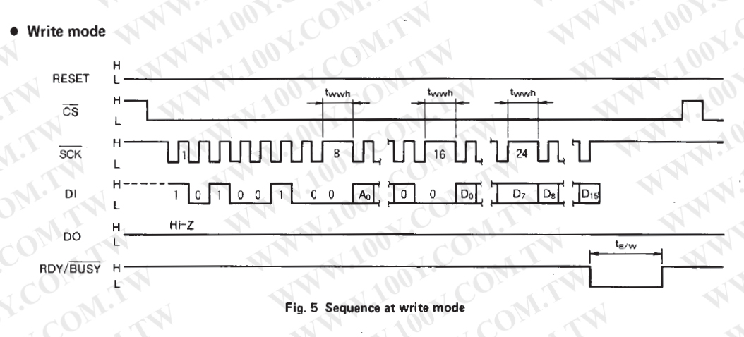 -------------------------------------------- ライト動作中にSCK(-)とDIを他のタスクに利用するには、 32番目のクロックの立ち上がりエッジからthwが経過したあとに CS(-)を"H"にする必要がある。Fig6参照。 To use SCK(-) and DI for other tasks during the write operation, CS(-) must be set to "H" after thw has elapsed from the rising edge of the 32nd clocks as shown in Figure 6. 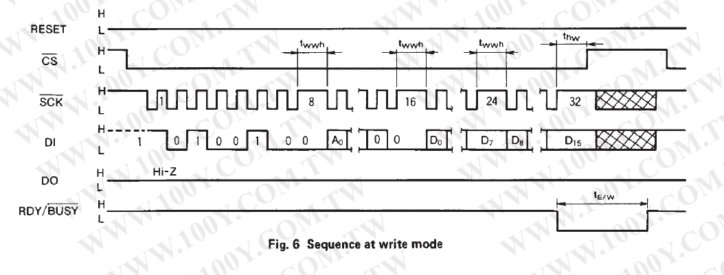 -------------------------------------------- ライト動作が始まった後、シーケンシャル・コントローラが 自動的にリセットされる。それでステータス・モードのリード動作は CS(-)が"H"に設定されずにライト動作が始まってから tSTAが経過したあとだと可能になる。 After write operation has started, the sequential controller is reset automatically, so read operation in the status mode become possible only after tSTA has elapsed from the time the write operation started without having to set CS(-) to "H". Before the status mode is set again, CS(-) must be set to "H" as in the ordinary mode setting procedure. 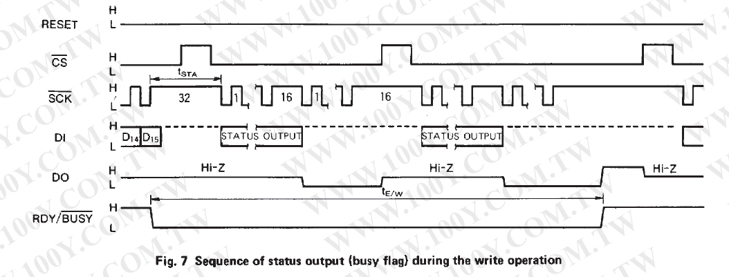 (2)CS(-)とRESETピンを接続している場合 ライト動作中、CS(-)=RESETピンは"L"に設定する必要がある。 上述のように一度ライト動作が始まると、 リード動作はSTATUSモードでのみ可能なので、 STATUSモードに設定していないときは、SCK(-)は"H"にしておく必要がある。 ライト動作中に、SCK(-)とDIを他のタスクに利用するには、FIG10をみろ。 During the write operation, the CS(-)=RESET pin must be set to "L". Because the read operation is possible only in the status mode once the write operation starts as described above, SCK(-) must be held to "H" when not setting the status mode. For using SCK(-) and DI for other tasks during the write opertion, see Figure 10. 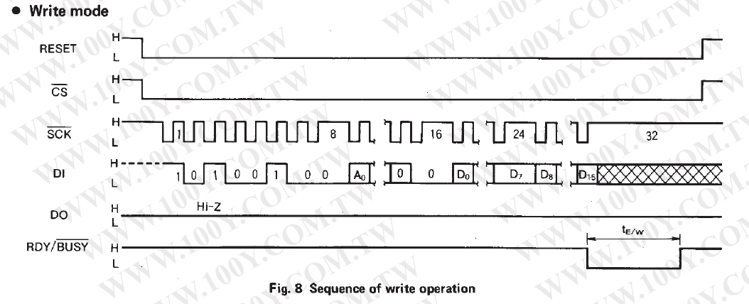 -------------------------------------------- ライト動作が始まった時間からtSTA時間経過したあとなら、 ステータス・モードでのリード動作が可能になる。 ステータス・モードがセットされた時は、DOピンはCS(-)が"H"にセットされるまで アウトプット状態になる。 The read operation in the status mode becomes possible after tSTA has elapsed from the time the write operation started. Attention is called to the fact, when the status mode is set, the DO pin is in the output state until CS(-) is set to "H". 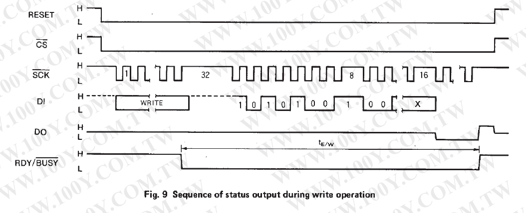 -------------------------------------------- Fig9のように、ステータス・モードのリード動作は、ライト動作が始まって からtSTA時間が経過したあとに可能になる。そしてステータスモードが セットされると、DOピンはアウトプット状態にセットされる。 SCK(-)とDIピンを他のタスクで使うのに加え、DOピンを使うと、 ライド動作が開始された時からtSTA時間が過ぎたあと、 ダミービットが入れられる。それは他のタスクが実行される前の ステータス・モードを避けるために。 ステータスモードのインストラクションコード(10101001)を 作らない限り、他のデータインプットはこの目的のために同じ効果である。 As shown in Figure9, the read operation in the status mode becomes possible after tSTA has elapsed from the time the write operation stated, and the DO pin is set to the output state when the status mode is set. When using the DO pin is addtion to the SCK(-) and DI pins for other tasks, a dummy bit input must be made after tSTA has elapsed from the time the write operation started to avoid the status mode before executing the other tasks. Other(than dummy bit) data input is equally effective for this purpose as log as it does not generate the status mode instruction code(10101001). 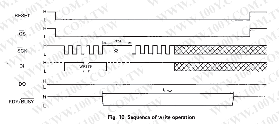 |
| 戻る |